Инструкция для Teka VR 90 4G AI TR AL
 1
1 2
2 3
3 4
4 5
5 6
6 7
7 8
8 9
9 10
10 11
11 12
12 13
13 14
14 15
15 16
16 17
17 18
18 19
19 20
20 21
21 22
22 23
23 24
24 25
25 26
26 27
27 28
28 29
29 30
30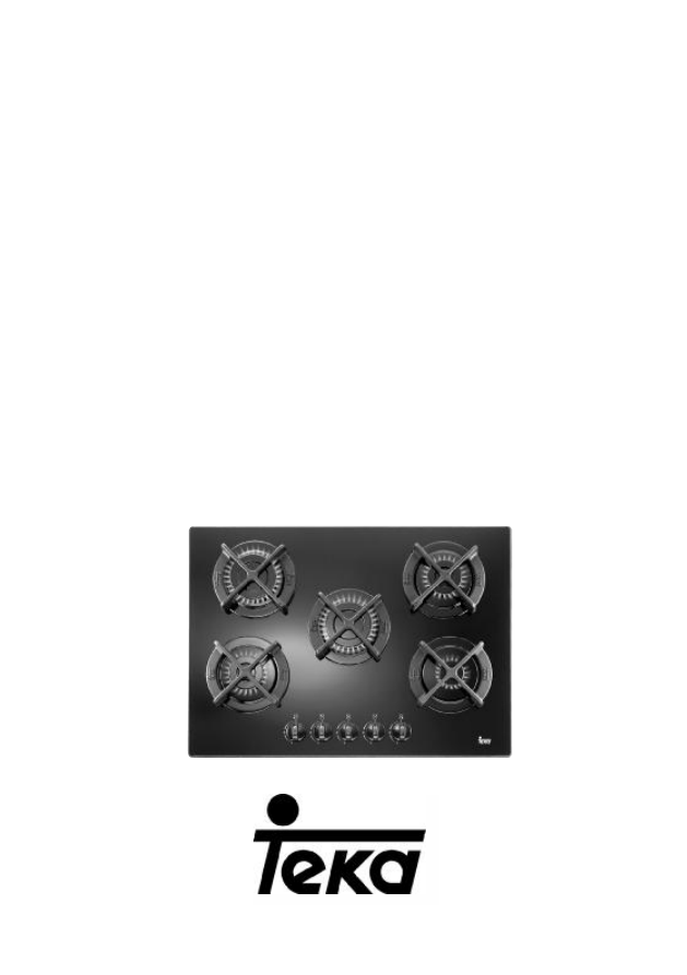
INSTALLATION INSTRUCTIONS
AND RECOMMENDATIONS FOR USE AND MAINTENANCE
GLASS GAS HOBS
EINBAU-ANLEITUNG
UND EMPFEHLUNGEN FÜR GEBRAUCH UND INSTANDHALTUNG
GAS-KOCHFELDER AUF GLAS
INSTRUCTIONS POUR L’INSTALLATION
ET RECOMMANDATIONS D’UTILISATION ET D’ENTRETIEN
PLAQUES DE CUISSON
CG.1 4G / CG.1 3G 1P
CG Lux-60 4G / CG Lux-70 4G / CG Lux-70 4G AI AL
CG Lux-70 5G / CG Lux-60 4G Al AL / CG Lux-70 5G Al AL
CG Lux-70 5G AI TR AL / CG Lux-70 5G TR / CGC 4G
CGC 4G AI AL / CG Lux-75 2G AI TR AL / CG Lux-86 3G AI TR AL
CG Lux-60 4G AI / CG Lux-70 4G AI / CG Lux-70 5G AI
CG Lux-70 5G AI TR / CG Lux-75 2G AI TR / CG Lux-86 3G AI TR
VR 90 4G AI TR AL / VR 90 4G AI TR
Оглавление инструкции
- Страница 1 из 31
INSTALLATION INSTRUCTIONS AND RECOMMENDATIONS FOR USE AND MAINTENANCE GLASS GAS HOBS EINBAU-ANLEITUNG UND EMPFEHLUNGEN FÜR GEBRAUCH UND INSTANDHALTUNG GAS-KOCHFELDER AUF GLAS INSTRUCTIONS POUR L’INSTALLATION ET RECOMMANDATIONS D’UTILISATION ET D’ENTRETIEN PLAQUES DE CUISSON CG.1 4G / CG.1 3G 1P CG
- Страница 2 из 31
- Страница 3 из 31
Contents / Inhalt / Table des Matières GB Introduction User Guide DE Page 5 10 Präsentation Hinweise zum Gebrauch Seite 5 31 Installation Positioning the hobs Positioning the oven Anchoring the hob Connecting the gas Connecting the electricity Gas conversion 11 11 12 12 15 16 16 Einbau Einbauort
- Страница 4 из 31
FR Présentation Guide d’utilisation 4 Page 5 54 Installation Logement des tables de cuisson Logement du four Ancrage de la table de cuisson Raccordement au gaz Branchement électrique Adaptation du gaz 55 55 56 56 60 60 61 Informations techniques Dimensions et puissances Caractéristiques techniques
- Страница 5 из 31
Introduction / Einführung / Présentation 1 2 1 2 3 4 3 4 CG.1 4G GB DE FR 1 Semi-rapid burner 1,500 Kcal/h -1.75 kW. 2 Auxiliary burner 860 Kcal/h - 1 kW. 3 Semi-rapid burner 1,500 Kcal/h -1.75 kW. 4 Rapid burner 2,580 Kcal/h -3 kW. * All the burners have a grid. * Maximum calorific power: 6,400
- Страница 6 из 31
1 2 2 1 5 3 4 3 CG-Lux-60 4G / CG Lux-60 4G Al AL / CG Lux-60 4G AI GB DE FR CGC 4G / CGC 4G AI AL GB 1 Rapid burner 2,580 Kcal/h - 3 kW. 2 Semi-rapid burner 1,500 Kcal/h -1.75 kW. 3 Semi-rapid burner 1,500 Kcal/h -1.75 kW. 4 Auxiliary burner 860 Kcal/h - 1 kW. * All the burners have a grid. *
- Страница 7 из 31
1 2 1 4 3 5 2 5 3 6 4 6 CG-Lux-70 5G TR / CG Lux-70 5G AI TR AL / CG Lux -70 5G AI TR CG-Lux-70 5G / CG Lux-70 5G Al AL / CG Lux -70 5G AI GB 1 Rapid burner 2,580 Kcal/h - 3 kW. 2 Semi-rapid burner 1,500 Kcal/h -1.75 kW. 3 Semi-rapid burner 1,500 Kcal/h -1.75 kW. 4 Auxiliary burner 860 Kcal/h - 1
- Страница 8 из 31
1 2 3 4 1 5 3 CG-Lux-70 4G / CG-Lux-70 4G AI AL / CG Lux -70 4G AI GB 1 Rapid burner 2,580 Kcal/h - 3 kW. 2 Semi-rapid burner 1,500 Kcal/h -1.75 kW. 3 Semi-rapid burner 1,500 Kcal/h -1.75 kW. 4 Auxiliary burner 860 Kcal/h - 1 kW. 5 Burner operating controls. * All the burners have a grid. * Maximum
- Страница 9 из 31
1 2 1 2 3 3 4 4 CG-Lux-86 3G AI TR AL / CG Lux-86 3G AI TR VR 90 4G AI TR AL / VR 90 4G AI TR GB 1 Triple crown burner 3,010 Kcal/h - 3.5 kW. 2 Triple crown burner 3,010 Kcal/h - 3.5 kW. 3 Semi-rapid burner 1,500 Kcal/h -1.75 kW. 4 Burner operating controls. * All the burners have a grid. * Maximum
- Страница 10 из 31
GB Guide to Using the Instructions Booklet Dear customer, Safety instructions We are delighted that you have put your trust in us. Before first use, you should carefully read the installation and connection instructions. We are confident that the new hob that you have purchased will fully satisfy
- Страница 11 из 31
Installation Important GB Minimum distances to walls fig. 10 INSTALLATION AND SETUP SHOULD BE CARRIED OUT BY AN AUTHORISED TECHNICIAN IN LINE WITH CURRENT INSTALLATION STANDARDS. Positioning the hobs Depending on the model to be installed, an opening with the dimensions shown in figure 11 will be
- Страница 12 из 31
GB Fitting holes fig. 11 the kitchen unit and in the adhesive on the decorative laminate of the worktop surface should be made to tolerate temperatures of up to 100ºC. TEKA assumes no responsibility for any malfunction or damage caused by faulty installation. PLEASE REMEMBER THAT THE GUARANTEE DOES
- Страница 13 из 31
GB Note: It is essential that the sealing washer is placed beneath the hob’s rim. If it is not placed there, the worktop could suffer extremely high temperatures. attaching the appropriate clip, depending on the worktop’s thickness (20, 30 and 40 mm) and tightening the screws until it is firmly
- Страница 14 из 31
GB ATTACHING THE HOB TO THE OVEN OR THE CONTROL PANEL The hob has four cardan telescopic shafts for this purpose. (See fig. 16). The way to join them is as follows: 1 Turn off the electricity (mods. CG.1 3G 1P and CGC 4G AI AL). 2 Detach the cardan telescopic shafts by pressing on the retention
- Страница 15 из 31
GB are those that are included with the hob - the ones that come with the oven can be discarded. This cooker includes caps for all TEKA ovens except models RT-600 and RT-800. Caps for these two models should be requested from the distribution outlet or the appropriate TEKA official technical
- Страница 16 из 31
GB If the flexible supply cable fitted to these appliances ever needs to be changed, it should be replaced by TEKA’s official service. Gas conversion Important! Any alteration that is to be made to the appliance to convert it to a different type of gas should only be carried out by a qualified
- Страница 17 из 31
GB Table 1 Burner Family Second Third Group H Group E+ Group 3+ Triple crown 135 T 135 T 95 Rapid 116 Y 116 Y 85 Semi-rapid 97 Z 97 Z 66 Auxiliary 72 X 72 X 50 Ø injector expressed in 1/100 mm. 17
- Страница 18 из 31
GB Technical Information Dimensions and powers Models CG.1 4G CG.1 3G 1P Dimensions in mm 590 590 Length Width 510 510 Height 163 163 Glass thickness 5 5 Dimensions of the space in the unit mm Length 570 570 Width 492 492 Depth 117 117 Power per burner and hotplate Triple crown gas burner 3,5 kW.
- Страница 19 из 31
GB Models CG Lux-70 CG Lux-70 CG Lux-70 CG Lux-75 CG Lux-86 4G AI 5G AI 5G AI TR 2G AI TR 3G AI TR CG Lux-70 CG Lux-70 CG Lux-70 CG Lux-70 CG Lux-70 CG Lux-75 CG Lux-86 4G AIAL 5G 5G AI AL 5G AI TR AL 5G TR 2G AI TR AL 3G AI TR AL Dimensions in mm Length 710 710 Width 510 510 Height 115 115 Glass
- Страница 20 из 31
GB Technical data COMMON FEATURES FOR ALL MODELS WITH ELECTRIC HOTPLATES AND AUTOMATIC IGNITION The supply voltage and frequency will be as shown on the rating plate. If an electric hotplate gets cracked, the hob should be disconnected from the electricity current. COMMON FEATURES FOR MODELS WITH
- Страница 21 из 31
Use and Maintenance GB fig. 18 Special requirements before starting for the first time Before connecting the hob to the electric mains, check that the voltage and frequency of the mains matches what is shown on the hob’s rating plate, which is located lower down, and on the guarantee or, where
- Страница 22 из 31
GB fig. 19 * Set the control to the position required. The ignition (ceramic and electrode) should be cleaned regularly and carefully in order to avoid ignition problems. Check, too, that the grooves in the burners have not become obstructed. Use flat-bottomed pans and check that they sit squarely
- Страница 23 из 31
GB for more than 15 seconds. If after 15 seconds the burner has not lit, stop the device and open the compartment door and/or wait at least 1 minute before attemting a futher ignition of the burner. In the event of the burner flames being accidentally extinguished, turn off the burner control and
- Страница 24 из 31
GB Anti-accidental turn system on gas controls fig. 22 On models without the safety system (without the gas cut-off device), the gas taps are equipped with a mechanical system that prevents the controls from being freely turned from the off position to the on position (and, therefore, prevents any
- Страница 25 из 31
GB fig. 24 Right fig. 25 Wrong Roasting dish, clay pots or utensils that reflect heat downwards Grid accessory * If you notice that the glass is broken or cracked, set all the hotplate controls to “zero” (turned off) turn off the gas tap and disconnect the electricity. Then contact TEKA’s Technical
- Страница 26 из 31
GB inspected by specialised Technical Service personnel at least once every 4 years. Maintenance of the electric hotplates (CG.1 3G 1P) Note: Any alteration or adjustment needed by the appliance should be made by authorised technical personnel. Suggestions for using the hotplates effectively To
- Страница 27 из 31
GB When cleaning the glass, the degree of soiling should be taken into consideration, and the following guidelines followed: * * * When soiling is light and not stuck fast, a damp cloth and a soft detergent can be used. * Staining or grease should be cleaned with cleaning products that are suitable
- Страница 28 из 31
GB * When cleaning the appliance with the burners removed, care should be taken not to allow liquid or other objects to get into the bend of the injector holder. * When cleaning, do not use products that can harm aluminium, such as soda, oil, etc. * Whenever you reassemble a burner, check that all
- Страница 29 из 31
Reminder GB Do not use small pans on large burners, or the flame will spread. Match pans to burners to make best use of the heat. Do not place the pan away from the centre of the burner. Place the pan properly, in the middle of the burner. Do not use utensils that reflect a lot of heat downwards
- Страница 30 из 31
GB If something doesn’t work Before calling the Technical Service, please make the following checks: Fault Possible cause Possible solution Neither the hotplates nor the pilot lights are working The cable is not connected to the mains There is no spark when the automatic ignition control is pressed
- Страница 31 из 31